DESCRIPTION :
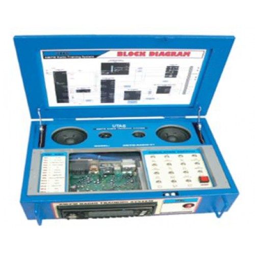
MZM-3004 has been designed from a Stereo Radio Tuner equipped with the most advanced reception circuits. Each one of the functional sections has several test points which permit the analysis and monitoring of the main electrical signals of the turner. All the test points are protected against accidental shorting.
FEATURES :
- Alternative frequency (AF)
- Digital Tuning
- Digital Signal Level Display
- Frequency range (FM, MW, LW)
- AM : 531-1,602 KHz, 153-279 KHz
- Direct through frequency introduction
- Automatic Broadcast Station search
- Menu Selection Display
- Preset FM and AM sections
FAULT SIMULATOR :
The fault simulator manipulates electric points of the tuner, to simulate real faults.
GENERAL SPECIFICATION :
- DC Output: 3.3V, 5V,8V 0.2A
- Operating temperature: 0 to 45C, 85% OR Less(R.H)
- Input Power:AC 240V, 50Hz 1-Phase
EXPERIMENT TOPICS
- Simulation on tuner fault.
- Simulation on audio amplifier fault.
- Simulation on Radio Data System (RDS) fault.
- Simulation on display panel fault.
- Simulation on radio receiver power supply fault.
- Simulation on the left channel fault.
- Simulation on the right channel fault.
- Simulation on AM/FM oscillator fault.
- Simulation on noise fault.
- Simulation on BEEP sound fault.
- Simulation on the disable FM fault.
- Simulation on the disable AM fault.
- Simulation on the key-0 fault.
- Simulation on the key-1 fault.
- Simulation on the key-2 fault.
- Simulation on reset switch.
- Waveform of oscillator input.
- Waveform of oscillator output.
- Waveform of filter signal.
BLOCK DIAGRAM
The block diagrams consist of the following functional modules :
- Tuner Section
- Automatic Tuning Section
- Sound control
- System control
- Mute control
- AGC Detector
- Over-Voltage Detector
- Power Amplifier
- Multiple Voltage Regulator
- Auxiliary Output Signal
- Audio Section
Send Enquiry
Your Name
Your Email
Tele Phone