MZFIRSTMOTION SDN BHD logo MZFIRSTMOTIONWe Never Stop Thinking
Analog Comunication Trainer
Electronic Engineering
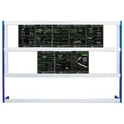
Analog Comunication Trainer

Model reference MZM-3006

  • Category: Electronic Engineering
  • Model reference: MZM-3006
  • Built to order in our Penang workshop
  • Delivery, installation and commissioning available
  • Lecturer training and documentation included

Price on application. Specifications can be adapted to your syllabus, supply voltage and laboratory space.

Specification

Description:

  • Design and implementation of second order active filters and RF oscillators.
  • Design and implementation of AM and FM modulator and demodulator.
  • Design and implementation of DSB/SC and SSB modulator and demodulator.
  • Design and implementation of TDM and FDM multiplexer and DE multiplexer.
  • Design and implementation of frequency converter and signal recovery

Features:

  • Textbook includes the theoretical and practical details.
  • Textbook includes the expected results for reference.
  • Problem discussion attached together with answers for instructor
  • Only need oscilloscope to obtain the measured results

MODULE

MODULE ONE:

1. Chapter1. : Second Order Active Filters Experiment:

  • Second Order Active Low-pass Filter
  • Second Order Active High-pass Filter
  • Second Order Active Band-pass Filter
  • Second Order Active Band-stop Filter

2. Chapter2. : RF Oscillators Experiment:

  • Colpitts Oscillator
  • Hartley Oscillator
  • Crystal Oscillator Voltage Controlled
  • Oscillator

MODULE TWO:

3. Chapter3: AM Modulator Experiment:

  • Transistor AM Modulator
  • MC1496 AM Modulator

4. Chapter4: AM Demodulator Experiment:

  • Diode Detector
  • Product Detector

MODULE THREE:

5. Chapter 5: DSB-SC and SSB Modulator Experiment:

  • DSB-SC Modulator
  • SSB Modulator

6. Chapter 6: DSB-SC and SSB Demodulator

Experiment:

  • Product detector of DSB-SC Demodulator
  • Product detector of SSB Demodulator

MODULE FOUR:

7. Chapter 7: FM Demodulator Experiment:

  • MC4046
  • FM Demodulator
  • LM565 FM Demodulator

8. Chapter 8: FM Modulator

Experiment:

  • MC4046 FM Modulator
  • LM566 FM Modulator

MODULE FIVE:

9. Chapter 9: TDM Multiplexer Experiment:

  • Waveform Generator
  • TDM Multiplexer

10. Chapter 10: TDM DE multiplexer Experiment:

  • TDM DE multiplexer

MODULE SIX

11. Chapter 11: FDM Multiplexer Experiment:

  • FDM Signal Generator
  • DSB-SC Modulated Signal Generator
  • FDM Multiplexer

12. Chapter 12: FDM Demodulator Experiment:

  • FDM DE multiplexer

MODULE SEVEN:

13. Chapter 13: Analog-to-digital Converter Experiment:

  • ADC0804 Analog-to-digital Converter
  • ADC0809 Analog-to-digital Converter

14. Chapter 14: Digital-to-analog Converter

Experiment:

  • R-2R Network DAC
  • DAC 0800 Converter

MODULE EIGHT:

15. Chapter15. : Frequency Converter Experiment:

  • Frequency Multiplier
  • Up/Down Frequency Converter

16. Chapter16. : Signal Recovery Experiment:

  • Carrier Signal Recovery Circuit
  • Clock Recovery Circuit

MODULE NINE:

DC POWER SUPPLY

Features:

1. Tipple Bipolar Voltage Output

  • DC 0 – 15V
  • DC + 5V
  • DC + 12V

2. Constant & Variable Voltage operation

3. Low Ripple and Noise

Function Generator

Features:

1. Two Signal Output Port

2. Frequency Range

  • 0 - 10Hz
  • 0 - 100kHz
  • 0 - 1kHz
  • 0 – 10kHz

3. Overload Protection

4. Waveform: Sine, Triangle, Square, TTL Pulse

5. Amplitude: 10Vpp

6. Built-in-6-Digit Frequency Counter

7. Two Large 0.5’’ LED Display

Send Enquiry Your Name
Your Email
Tele Phone

Want this adapted to your lab?

Tell us the experiments, the class size and the space you have. We will quote the unit built to match.